
Explain the principle ,working and construction of moving coil galvanometer.

Shehnaaz Shareen answered this
Principle:
Its working is based on the fact that when a current carrying coil is placed in a magnetic field, it experiences a torque.

Working:
Suppose the coil PQRS is suspended freely in the magnetic field.
Let
l = Length PQ or RS of the coil
b = Breadth QR or SP of the coil
n = Number of turns in the coil
Area of each turn of the coil, A = l × b
Let B = Strength of the magnetic field in which coil is suspended
I = Current passing through the coil in the direction PQRS
Let, at any instant, α be the angle which the normal drawn on the plane of the coil makes with the direction of magnetic field.
The rectangular coil carrying current when placed in the magnetic field experiences a torque whose magnitude is given by,
τ = nIBA sinα
Due to deflecting torque, the coil rotates and suspension wire gets twisted. A restoring torque is set up in the suspension wire.
Let θbe the twist produced in the phosphor bronze strip due to rotation of the coil and K be the restoring torque per unit twist of the phosphor bronze strip. Then,
Total restoring torque produced = kθ
In equilibrium position of the coil,
Deflecting torque = Restoring torque
∴ NIBA = kθ
Or, ![]()
Where, ![]() [constant for a galvanometer]
[constant for a galvanometer]
It is known as galvanometer constant.
Current sensitivity of the galvanometer is the deflection per unit current.

Voltage sensitivity is the deflection per unit voltage.

- 144
Shehnaaz Shareen answered this
Conversion of a galvanometer to ammeter

A shunt (low resistance) is connected in parallel with the galvanometer.

Where,
I → Total current in circuit
G → Resistance of the galvanometer
S →Resistance of the shunt
Ig → Current through galvanometer
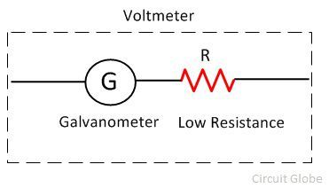
Conversion of galvanometer to voltmeter

A high resistance is connected in series with the galvanometer.

Where,
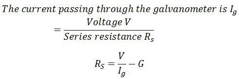
V → Potential difference across the terminal A and B
Ig → Current through the galvanometer
R → High resistance
G → Resistance of galvanometer
- 30
Jenny answered this
R=V/Ig-G
- -6
Pushpita Deb answered this
I = k * (alpha) / NAB
- -9
Fun answered this
- -7
Tajummal answered this
- -7
Vikas answered this
- -7
Sai Ramya answered this
- -9
Rahul R Kashyap answered this
radial magnetic field. The coil is wrapped on a cylindrical soft iron core which enables the field to remain radial
in all positions of the coil.
When a current flows through the coil, a torque acts on it.
M B
= NIAB sin
Here the symbols have their usual meaning. Since field is parallel to the plane of the coil at all positions
= 90° ( is angle between area vector and magnetic field) and = NIAB. The magnetic torque tends
to rotate the coil.
A spring Sp provides a counter torque K that balances the magnetic torque NIAB, resulting in a steady angular
deflection . In equilibrium
K = NIAB
where, K is torsional constant of the spring, that is restoring torque per unit twist. The deflection is indicated
on the scale by a pointer attached to the spring. We have
NAB
I
K
⎛ ⎞ ⎜ ⎟
⎝ ⎠
The quantity in brackets is a constant for a given galvanometer
- 6
Amana Chotte answered this
- 0
Amana Chotte answered this
- -2
Preeti answered this
- -6
Tanishk answered this
- -12
Praisy Jiji answered this
It's working principle is that,a current carrying rectangular loop placed in a magnetic field experiences a torque.
It consist of a coil of many turns free to rotate about an axis in a uniform radial magnetic field.
- -5
Vennela answered this
construction ::
- It consits of a rectangular coil of fine insulated copper wire wounded on a light Al frame
- A motion of coil is controlled by the pair of heir springs of phosphorous and bronze
- The springs experiences a restoring torque and can serve as current leads
- A light Al pointer is attached to the coil to measure its deflection on a suitable scale
- A symmentrical coil is placed between the concave poles of horshoe permanent magnets
- There is a symmentrical soft iron core which not only makes the coil radial but also increases the magnetic strength
when coil is placed in a magnetic field it experiences a torque
so,
T=F*perpendicular distance
T=NIBb*sin90
T=NIB(ab)
T=NIBA
HOPE IT HELPFUL FRNDS!!!
ALL THE VERY BEST FRNDS
- 34
Sanket Shahane answered this
yes, it is very useful bcoz it was asked in our intermediate exams
- -7
Alrafi answered this
- -6
S.tejas answered this
Even mine is not answered!
- 0
Kumar Aryan answered this
IN A GALVANOMETER , THERE IS A NEEDLE ATTACHED TO A COIL, WHICH IS SUBJECT TO A MAGNETIC FIELD.ATTACHED TO THE COIL IS A SPRING SIMILAR TO THE HAIRSPRING ON THE BALANCE WHEEL OF A WATCH.
IN EQUILIBRIUM POSITION WITH NO CURRENT IN THE COIL, THE NEEDLE IS AT ZERO. WHEN THERE IS CURRENT IN THE COIL, MAGNETIC FIELD EXERTS A TORQUE ON IT , WHICH IS PROPORTIONAL TO THE CURRENT. THIS TORQUE IS RESPONSIBLE FOR THE ROTATION OF THE COIL AND HENCE THE NEEDLE DEFLECTS. AS HE COIL TURNS , THE SPRING EXERTS A RESONATING TORQUE THAT IS PROPORTIONAL TO THE ANGULAR DISPLACEMENT.
IT CONSISTS OF A SCALE, SPRING,POINTER,SOFT IRON CORE,MAGNETIC FIELD,PIVOTED COIL AND A PERMANENT MAGNET.
- -5
Vhy answered this
- -4
Honey answered this
- -10
Shriram Iyer answered this
Working:
l = Length PQ or RS of the coil
Area of each turn of the coil, A = l × b
Let, at any instant, α be the angle which the normal drawn on the plane of the coil makes with the direction of magnetic field.
Due to deflecting torque, the coil rotates and suspension wire gets twisted. A restoring torque is set up in the suspension wire.
In equilibrium position of the coil,
Or, 
-
Current sensitivity of the galvanometer is the deflection per unit current.
-
Voltage sensitivity is the deflection per unit voltage.
- -6
Shriram Iyer answered this
Working:
l = Length PQ or RS of the coil
Area of each turn of the coil, A = l × b
Let, at any instant, α be the angle which the normal drawn on the plane of the coil makes with the direction of magnetic field.
Due to deflecting torque, the coil rotates and suspension wire gets twisted. A restoring torque is set up in the suspension wire.
In equilibrium position of the coil,
Or,
-
Current sensitivity of the galvanometer is the deflection per unit current.
-
Voltage sensitivity is the deflection per unit voltage.
- -2
Mehibiz Sultana answered this
- -5
Anuradha Narayanan answered this
- -8
Himanshu answered this


- 26
Zeba Kausher answered this
- -4
Vairagade.sridhar answered this
- -8
Devdatta Biswas answered this
Galvanometer is device used to detect current in a circuit.
Principle: A current carrying coil placed in a magnetic field experiences a current dependent torque which tends to rotate the coil, and thus produces an angular deflection.
Construction: A Weston (pivoted-type)(used in laboratories) galvanometer consists of a rectangular coil of insulated copper wire wound on a light non magnetic metallic (Aluminium) frame. This frame has got an axle. Both the ends of this axle are pivoted by jeweled bearings. The motion of the coil is controlled by a pair of hair springs of phosphor- bronze on both the ends which provide the restoring torque for the coil. These springs also act as current leads. A light aluminium pointer is also attached to the coil which helps to measure the deflection of the coil on the measuring scale. The coil is symmetrically placed between two cylindrical horse shoe magnets or, pole pieces of a strong permanent horse-shoe magnet. A cylindrical soft iron-core is also mounted. Since it has been mounted symmetrically between the concave cylindrical poles, the magnetic lines of force are allowed to act along the radius of the iron core. Thus, we get a radial magnetic field. The soft iron core due to its high permeability, intensifies the magnetic field. This increases the sensitivity of the galvanometer.

Theory and working:
Let:
I = current through the coil
a,b = Sides of the coil where, b is the side facing the magnets
A = ab = Area of the rectangular coil
N = Number of turns in the coil
As the magnetic field is radial, at every instant of time, the plane of the coil would be parallel to the magnetic field. The side a will also remain parallel to the magnetic field. Thus, the side a will not experience any force by the magnetic field. However, the side “b” of the coil would remain perpendicular to the magnetic field and thus experience a force. From Fleming’s left hand rule, we see that the two opposite “b” sides of the rectangular coil would experience equal and opposite force. This will constitute a couple and this will produce a torque.
This torque,
t = Force x perpendicular distance between the lines of action of the two forces
= BIbN x a sin(theta) where theta is the angle between the area vector and the magnetic field which is 90 degrees
So, the torque = BIbN x a = BINA
This torque deflects the coil by an angle alpha. A restoring torque acts on the coil, by the hair springs such that, restoring torque = k.alpha
where k is the torsion constant of the spring
Now, in equilibrium position,
k.alpha = BINA
Thus, alpha is directly proportional to I.
Thus, alpha = (NBA/k).I
Or, I = (k/NBA).alpha
Or, I = G.alpha
G is a constant, called Galvanometer constant and is constant for a galvanometer.
Meanwhile, the current which produces a deflection of one scale division is termed as the Figure of Merit of the galvanometer.
Sensitivity of a galvanometer: A galvanometer is said to be sensitive if it shows a large scale deflection even when a small amount of current is passed through it, or a small amount of voltage is applied across it.
CURRENT SENSITIVITY: The amount of deflection shown by a galvanometer when a unit current is passed through it. I(s) = alpha/I
VOLTAGE SENSITIVITY: The amount of deflection shown by a galvanometer when a unit potential difference is applied across the ends of the galvanometer. V(s) = alpha/V =alpha/IR = I(s)/R
[where, alpha = (NBA/k).I ]
Thus the factors on which the sensitivity of a moving coil galvanometer depends on, are:
1. Number of turns of the coil, N
2. Strength of magnetic field, B
3. Area of the rectangular coil, A
4. Torsion constant of the spring and the suspension wires, k
- 5
Skowshika answered this
- -2
Abhilash S answered this
Cyclotron is a device used to accelerate charged particles to high energies. It was devised by Lawrence.
Principle
Cyclotron works on the principle that a charged particle moving normal to a magnetic field experiences magnetic lorentz force due to which the particle moves in a circular path.
Construction
 It consists of a hollow metal cylinder divided into two sections D1 and D2 called Dees, enclosed in an evacuated chamber (Fig 3.21). The Dees are kept separated and a source of ions is placed at the centre in the gap between the Dees. They are placed between the pole pieces of a strong electromagnet. The magnetic field acts perpendicular to the plane of the Dees. The Dees are connected to a high frequency oscillator.
Working:
When a positive ion of charge q and mass m is emitted from the source, it is accelerated towards the Dee having a negative potential at that instant of time. Due to the normal magnetic field, the ion experiences magnetic lorentz force and moves in a circular path. By the time the ion arrives at the gap between the Dees, the polarity of the Dees gets reversed. Hence the particle is once again accelerated and moves into the other Dee with a greater velocity along a circle of greater radius. Thus the particle moves in a spiral path of increasing radius and when it comes near the edge, it is taken out with the help of a deflector plate (D.P). The particle with high energy is now allowed to hit the target T.
When the particle moves along a circle of radius r with a velocity v, the magnetic Lorentz force provides the necessary centripetal force.
Bqv = (vm2 ) / r
v /r = Bq / m = constant ...(1)
The time taken to describe a semi-circle
t = π r / v (2)
Substituting equation (1) in (2),
t = π m/ Bq .. (3)
It is clear from equation (3) that the time taken by the ion to describe a semi-circle is independent of
(i) the radius (r) of the path and (ii) the velocity (v) of the particle
Hence, period of rotation T = 2t
T = 2 π m / Bq = constant ...(4)
So, in a uniform magnetic field, the ion traverses all the circles in exactly the same time. The frequency of rotation of the particle,
v = 1 /T = Bq / 2 πm .. (5)
If the high frequency oscillator is adjusted to produce oscillations of frequency as given in equation (5), resonance occurs.Cyclotron is used to accelerate protons, deutrons and α - particles.

Limitations
a. Maintaining a uniform magnetic field over a large area of the Dees is difficult.
b. At high velocities, relativistic variation of mass of the particle upsets the resonance condition.
c. At high frequencies, relativistic variation of mass of the electron is appreciable and hence electrons cannot be accelerated by cyclotron.
- 2
Anmol answered this
- -1
Kirthik answered this
FOR A CLEAR EXP
- -1
Nonu answered this
and helpful also
- -3
Rishab answered this
- 1
Hrithik Dhull answered this
- -2
Varun answered this

- -2
Pinky answered this
- -2
Karthik answered this

- 0
Shailesh Varma answered this
- -1
Yashika Malhotra answered this

Try this app and learn from teachers and students of 100+ schools from all over India.
I am just loving this app, It has 20,000+ free video courses to learn from
- -2
Muskan Tyagi answered this
- -1
Muskan Tyagi answered this
- -1
Indradeo Rajak answered this
- -4
Badri Vishal answered this

- 19
Bharat Mittal answered this
- -2
Mahesh answered this
- -1
Harrypotter answered this
- -2
Harrypotter answered this

- -2
Himaja Manapragada answered this

- 3
Himaja Manapragada answered this

- -2
Himaja Manapragada answered this
- -3
Himaja Manapragada answered this

- -2
Sayan Rakshit answered this
- -3
Balaji K answered this
- -1
Johnpaul answered this
- -1
Ashutosh Verma answered this
Galvanometer
Definition: The galvanometer is the device used for detecting the presence of small current and voltage or for measuring their magnitude. The galvanometer is mainly used in the bridges and potentiometer where they indicate the null deflection or zero current.
Principle of Galvanometer
The potentiometer is based on the premise that the current sustaining coil is kept between the magnetic field experiences a torque.
Construction of the Galvanometer
The construction of the potentiometer is shown in the figure below.
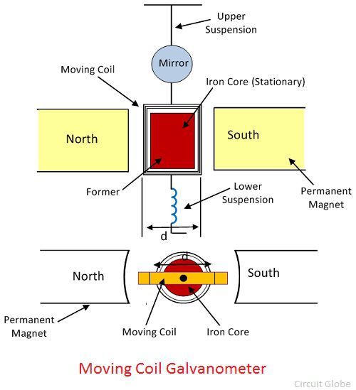 The moving coil, suspension, and permanent magnet are the main parts of the galvanometer.
Moving Coil – The moving coil is the current carrying part of the galvanometer. It is rectangular or circular and has the number of turns of fine copper wire. The coil is freely moved about its vertical axis of symmetry between the poles of a permanent magnet. The iron core provides the low reluctance flux path and hence provides the strong magnetic field for the coil to move in.
Suspension – The coil is suspended by a flat ribbon which carries the current to the coil. The other current carrying coil is the lower suspension whose torque effect is negligible. The upper suspension coil is made up of gold or copper wire which is made in the form of a ribbon. The mechanical strength of the wire is not very strong, and hence the galvanometers handle carefully without any jerks.
Mirror – The suspension carries a small mirror which casts the beam of light. The beam of light placed on the scale on which the deflection is measured.
Torsion Head – The torsion head is used for controlling the position of the coil and for adjusting the zero setting.
Applications of Galvanometer
The galvanometer has following applications. They are
- It is used for detecting the direction of current flows in the circuit. It also determines the null point of the circuit. The null point means the situation in which no current flows through the circuit.
- It is used for measuring the current.
- The voltage between any two points of the circuit is also determined through galvanometer.
Working of Galvanometer
Let, l, d – the length of respective vertical and horizontal side of the coil in the meter.
N – number of turns in the coil,
B – Flux density in the air gap, wb/m2
i – current through moving coil in Ampere
K – spring constant of suspension, Nm/rad
θf – final steady-state deflection of moving coil in radiance
When the current flows through the coil, it experiences a torque which is expressed as
![]() The force on each side of the coil is given as,
The force on each side of the coil is given as,![]() Hence deflecting torque becomes,
Hence deflecting torque becomes, ![]()
![]() Where,
Where, ![]() N, B, A are the constant of the galvanometer.
N, B, A are the constant of the galvanometer.
![]() The G is called the displacement constant of the galvanometer, and their value is equal NBA = NBld.
The G is called the displacement constant of the galvanometer, and their value is equal NBA = NBld.
The controlling torque exerted by the suspension at deflection θF is![]() For final steady deflection,
For final steady deflection,  Hence final steady deflection,
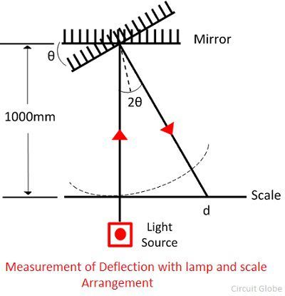
 For the small deflection angle, the deflection is expressed as the product of the radius and angle of the turned. By the reflected beam, it is expressed as 1000 Χ 2θF = 2000 Gi / K in millimetre.
The above equation shows that when the mirror turns through an angle θF the reflected beam turns through an angle 2θF shown in the figure below.
 Conversion of Galvanometer into an Ammeter
The galvanometer is used as an ammeter by connecting the low resistance wire in parallel with the galvanometer. The potential difference between the voltage and the shunt resistance are equal.
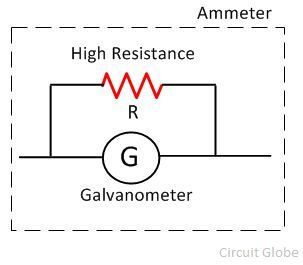
Where, S = shunt resistance and Is = current across the shunt.
As the galvanometer and the shunt resistance are connected in potential with the circuit, their potentials are equal.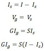
Thus, the shunt resistance is given as, 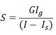
The value of the shunt current is very small as compared to the supply current.
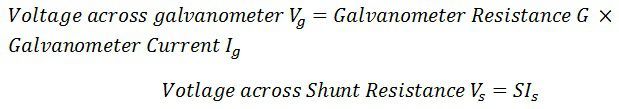
Conversion of Galvanometer into a voltmeter
The galvanometer is used as a voltmeter by connecting the high resistance in series with the circuit.
The range of the voltmeter depends on the value of the resistance connected in series with the circuit.
- 2
Salman Ahmad answered this
- 2
Fawwaz answered this
- -2
Anjali Gupta answered this
- 0
Sruthi Tummalapalli answered this
that big one
- 4
Vikrant Thakur answered this

- -1
Deepa answered this
Principle and working : A current carrying coil placed in a uniform magnetic field, can experience a torque.
consider a rectangular coil for which no. or turns = N,
Area of cross-section = l x b = A,
Intensity of the uniform magnetic field = B,
Current through the coil = I
(k = restoring torque per unit twist)
The deflection of the coil is therefore, proportional to the current flowing through it.
- 8
Deepa answered this
- 2
Saqlain Farooq answered this

- 0
Khagendra answered this
- 1
Hiten Agarwal answered this
- 2
Aiza Eman answered this
- 1
Pranav Devdhar answered this

- 1
Manshu Drall answered this

- 0
Satya answered this
- 0
The Dominant answered this
- 0
Suyog Date answered this
- 0
Sarangapani Bardoloi answered this

- 3
Deepali Prasad answered this

- 1
Sanaya answered this

- 1
Ambedkar answered this

- 2
Ambedkar answered this

- 4
Rohit answered this
- 0
Shanmathi answered this

- 0
ambrishanada... answered this

- 4
Abhi answered this
Principle
Torque?acts on a current carrying coil suspended in the uniform magnetic field. Due to this, the coil rotates. Hence, the deflection in the coil of a moving coil galvanometer is directly proportional to the current flowing in the coil.
?
[source: Redefining The Knowledge]
The Moving Coil Galvanometer
Construction
It consists of a rectangular coil of a large number of turns of thinly insulated copper wire wound over a light metallic frame. The coil is suspended between the pole pieces of a horseshoe magnet by a fine phosphor ? bronze strip from a movable torsion head. The lower end of the coil is connected to a hairspring of phosphor bronze having only a few turns.
The other end of the spring is connected to a binding screw. A soft iron cylinder is placed symmetrically inside the coil. The hemispherical magnetic poles produce a radial?magnetic field?in which the plane of the coil is parallel to the magnetic field in all its positions. A small plane mirror attached to the suspension wire is used along with a lamp and scale arrangement to measure the deflection of the coil.
- 0
Nishant Singh answered this
- 0
Shivangi answered this

- 0
Alok Rawat answered this

- 0
adarshsingh8853757189... answered this
- 0
adarshsingh8853757189... answered this
- 0
Menka Bhatia answered this

- 0
Ajomina answered this
Galvanometer is device used to detect current in a circuit.
Principle: A current carrying coil placed in a magnetic field experiences a current dependent torque which tends to rotate the coil, and thus produces an angular deflection.
Construction: A Weston (pivoted-type)(used in laboratories) galvanometer consists of a rectangular coil of insulated copper wire wound on a light non magnetic metallic (Aluminium) frame. This frame has got an axle. Both the ends of this axle are pivoted by jeweled bearings. The motion of the coil is controlled by a pair of hair springs of phosphor- bronze on both the ends which provide the restoring torque for the coil. These springs also act as current leads. A light aluminium pointer is also attached to the coil which helps to measure the deflection of the coil on the measuring scale. The coil is symmetrically placed between two cylindrical horse shoe magnets or, pole pieces of a strong permanent horse-shoe magnet. A cylindrical soft iron-core is also mounted. Since it has been mounted symmetrically between the concave cylindrical poles, the magnetic lines of force are allowed to act along the radius of the iron core. Thus, we get a radial magnetic field. The soft iron core due to its high permeability, intensifies the magnetic field. This increases the sensitivity of the galvanometer.
- -1
Henderson Inka answered this
a) identify the equipotential surface of the system at every point of the surface
b) give direction of the Electric field
- 1
Yogesh Malik answered this
- 0
Disha answered this

- 3
Gaganjot answered this

- 0
Kiran Kiran Singh answered this
- 0
Deepak answered this
- 0
Deepak answered this
- 0
Parveen Kumar answered this
A current-carrying coil when placed in an external magnetic field experiences magnetic torque. The angle through which the coil is deflected due to the effect of the magnetic torque is proportional to the magnitude of current in the coil.
Working of Moving Coil Galvanometer
When a galvanometer is connected to a current carrying circuit, a current flows in the coil of the galvanometer.? Since the coil is suspended in a magnetic field, a?deflecting torque?acts upon it. Due to this torque, coil starts rotating from its position.
?
As the coil rotates, the controlling springs are twisted and an elastic restoring torque is developed in them and it opposes the rotation of the coil. This torque is proportional to the angle of rotation of the coil.
?
When the restoring torque (i.e.?controlling torque) becomes equal to the?deflecting torque, the coil rests in equilibrium position.
?
A galvanometer is used in electrical circuits to detect?current, and in experiments to determine the null point.
?
If somehow a heavy current happens to flow into the coil of the galvanometer, then due to very large deflection the pointer of the galvanometer may strike the ?stop pin? and be broken, or coil of the galvanometer may burn due to excessive heat produced.
?
To save the galvanometer from these possible damages, a thick wire or strip of copper is connected in parallel with its coil. It is known as ?shunt?.? Its resistance is very small as compared to the resistance of the coil. Therefore, most part of the current goes through the shunt and only a very small part goes through the coil. Hence, there are no chances of damage to the coil or pointer.
?
Shunted-galvanometer is very useful for determining the null-point in experiments. First, the approximate position of the null-point is determined by using the shunted-galvanometer. At this stage, the current in the circuit is very feeble. Now the shunt is removed from the galvanometer so that full current goes through the galvanometer and accurate position of the null-point is determined.
Moving-coil Galvanometer Construction
It consists of a coil having a large number of turns of fine insulated copper wire wound on an aluminum frame.
?
The ends of the axle of the aluminum frame are inserted in two pivots so that the coil may rotate about the axle. At both ends of the coil, near the pivots, two springs are attached which produce a controlling torque on the moving system and connect the coil to the outer circuit.
?On both sides of the coil, there are pole-pieces of a permanent strong horseshoe magnet. The coil rotates in the magnetic field of these pole pieces.
?
??To read the deflection of the coil, a pointer is attached to the coil which moves over a circular scale. The divisions on the scale are made at equal distances and the zero point is in the center. That is why no positive and negative signs are marked at the terminal screws of the galvanometer. It can measure currents up to 10-6?A.
- 0
Tannu answered this
- 0
Tannu answered this
abiotic element.

- 0
Diptichand answered this

- 0
Neev Patel answered this

- 0
Shivani answered this

- 0
Jahirul Islam answered this

- 0
Dhruv Kumar Singhi answered this
- 0
Kundan Mehta answered this
- 0
Usha M S Usha answered this
- 0
Abu Raihan Ahmed answered this
- 0
Mahendra Baviskar answered this
- 0
Deepika Sanguri answered this

- 0
Kanishka answered this

- 0
Mohammad Azam answered this
- 0
Jhansi answered this
- 0
Jhansi answered this
- 0
Ashirbad Maharana answered this
- 0
Isha answered this
- 0
Kuldeep Kumar answered this
Construction: It consists of a circular coil of insulated copper wire wound on a circular non magnetic frame. The frame is mounted vertically on a horizontal base provided with leveling screws on the base. The coil can be rotated on a vertical axis passing through its centre. A compass box is mounted horizontally at the centre of a circular scale. The compass box is circular in shape. It consists of a tiny, powerful magnetic needle pivoted at the centre of the coil. The magnetic needle is free to rotate in the horizontal plane. The circular scale is divided into four quadrants. Each quadrant is graduated from 00 to 900. A long thin aluminium pointer is attached to the needle at its centre and at right angle to it. To avoid errors due to parallax a plane mirror is mounted below the compass needle.
Working: The current to be measured is now sent through the coil, and produces a magnetic field, perpendicular to the plane of the coil, and directly proportional to the current. The magnitude of the magnetic field produced by the coil is B; the magnitude of the horizontal component the earth's magnetic field is BH. The compass needle aligns itself along the vector sum of B and BH after rotating through an angle theta from its original orientation, such that, tan theta = B/BH. Since the magnetic field of the earth is constant, and B depends directly on the current, the current is thus proportional to the tangent of the angle through which the needle has turned.
- 0
Mohd Aneesg answered this
- 0
Shriya Wankhade answered this
- 0
Happy Singhsher Gill answered this
- 0
Ankityadav answered this

- 0
Ankityadav answered this
- 0
Ankityadav answered this

- 0
Sonu Kumar Dubey answered this
- 0
Sunil answered this
- -1
Prabudhdev answered this

- 0
Sashikumar answered this

- 0
Sashikumar answered this
- 0
Diksha answered this
- 0
Riya Singh answered this
- 0
F You answered this

- 0
Mahesh Patel answered this
- 0
Deepu Raj answered this
- 0
Poonam answered this

- 0
Awanish answered this

- 0