

Kranav Sharma answered this
You can refer to the following link
Half and Full Wave Rectifiers (scroll down to near the bottom)
@Zaara! Thanks for the hard work, much appreciated.
- 0
Zaara .....khan answered this
Half-wave rectification
In half wave rectification, either the positive or negative half of the AC wave is passed, while the other half is blocked. Because only one half of the input waveform reaches the output, it is very inefficient if used for power transfer. Half-wave rectification can be achieved with a single diode in a one-phase supply, or with three diodes in a three-phase supply. Half wave rectifiers yield a unidirectional but pulsating direct current.

The output DC voltage of a half wave rectifier can be calculated with the following two ideal equations:[1]


[edit]Full-wave rectification
A full-wave rectifier converts the whole of the input waveform to one of constant polarity (positive or negative) at its output. Full-wave rectification converts both polarities of the input waveform to DC (direct current), and is more efficient. However, in a circuit with a non-center tapped transformer, four diodes are required instead of the one needed for half-wave rectification. (See semiconductors,diode). Four diodes arranged this way are called a diode bridge or bridge rectifier.

For single-phase AC, if the transformer is center-tapped, then two diodes back-to-back (i.e. anodes-to-anode or cathode-to-cathode) can form a full-wave rectifier. Twice as many windings are required on the transformer secondary to obtain the same output voltage compared to the bridge rectifier above.


A very common vacuum tube rectifier configuration contained one cathode and twin anodes inside a single envelope; in this way, the two diodes required only one vacuum tube. The 5U4 and 5Y3 were popular examples of this configuration.


For three-phase AC, six diodes are used. Typically there are three pairs of diodes, each pair, though, is not the same kind of double diode that would be used for a full wave single-phase rectifier. Instead the pairs are in series (anode to cathode). Typically, commercially available double diodes have four terminals so the user can configure them as single-phase split supply use, for half a bridge, or for three-phase use.

Most devices that generate alternating current (such devices are called alternators) generate three-phase AC. For example, an automobile alternator has six diodes inside it to function as a full-wave rectifier for battery charging applications.
The average and root-mean-square output voltages of an ideal single phase full wave rectifier can be calculated as:
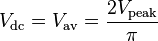

For an ideal three-phase full wave rectifier, the average output voltage is

Where:
- Vdc, Vav - the average or DC output voltage,
- Vp - the peak value of half wave,
- Vrms - the root-mean-square value of output voltage.
- π = ~ 3.14159
- α = firing angle of the thyristor (0 if diodes are used to perform rectification)
- 4