
![]()
![]()
![]()
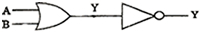
- Name the gate obtained from the combination of gates shown in the figure. Draw its logic symbol. Write the truth table of the combination.
- Draw a circuit diagram for use of NPN transistor as an amplifier in common emitter configuration. The input resistance of a transistor is1000Ω. On changing its base current by 10µA, the collector current increases by 2 m A. If a load resistance of 5 kΩ is used in the circuit, calculate:
- the current gain
- voltage gain of the amplifier.
- When an inductor L and a resistor R in series are connected across a 12 V, 50Hz supply, a current of 0.5 A flows in the circuit. The current differs in phase from applied voltage by π/3 radian. Calculate the value of R.
- Two cells of emf 1.5 V and 2 V and internal resistance 1 ohm and 2 ohm respectively are connected in parallel to pass a current in the same direction through an external resistance of 5 ohm.
- Draw the circuit diagram.
- Using Kirchhoff's laws, calculate the current through each branch of the circuit and potential difference across the 5 ohm resistor.
- A galvanometer with a coil of resistance 120 ohm shows full scale deflection for a current of 2.5 mA. How will you convert the galvanometer into an ammeter of range 0 to 7.5 A? Determine the net resistance of the ammeter. When an ammeter is put in a circuit, does it read slightly less or more than the actual current in the original circuit? Justify your answer.
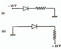
- Explain, with the help of a circuit diagram, how the thickness of depletion layer in a p-n junction diode changes when it is forward biased. In the following circuits which one of the two diodes is forward biased and which is reverse biased?
- In a series R - C circuit, R= 30Ω, C= 0.25µF, V= 100 V and ω= 100 rad/second. Find the current in the circuit and calculate the voltage across the resistor and the capacitor.
Is the algebraic sum of these voltages more than the source voltage? If yes, resolve the paradox. - In a double slit experiment with monochromatic light, fringes are obtained on a screen placed at some distance from the slits. If the screen is moved by 5 x 10⁻²m towards the slits, the change in fringe width is 3x 10⁻⁵m. If the distance between slits is 10-3m, calculate the wavelength of light used.
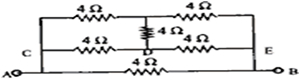
- Six resistors, each of value 4Ω are joined together in a circuit as shown in the figure. Calculate equivalent resistance across the points A and B. If a cell of emf 2V is connected across AB, compute the current through the arms AB and DF of the circuit.
- The horizontal component of the earth's magnetic field at a given place is 0.4×10⁻²Wb/m2and angle of dip is 300. Calculate the value of
- vertical component,
- the total intensity if the earth's magnetic field.
- Calculate the temperature at which the resistance of a conductor becomes 20% more than its resistance at 270C. The value of the temperature coefficient of resistance of the conductor is 2.0×10⁻²/k.
- A 8Ω resistance wire is bent at the middle by 1800. Both the halves are twisted together. What is the new resistance?
- A galvanometer with a coil of resistance 12Ω shows the full scale deflection for a current of 2.5 mA. How will you convert the galvanometer into
- an ammeter of range 0 to 7.5A,
- voltmeter of range 0 to 10 v?
- In a young’s double slit experiment, the slit are separated by 0.28 mm and the screen is placed 1.4m away. The distance between the central bright fringe and the fourth bright fringe is measured to be 1.2 cm. Determine the wavelength of light used in the experiment.
- A 25 µF capacitor, a 0.10 henry inductor and a 25 ohm resistor are connected in series with an a.c. source, whose emf is given by E= 310 sin314t volts
- What is frequency of the emf?
- What is impedance of the circuit?
- What is the phase angle of the current by which it leads or lags the applied e.m.f?
- what is expression for the instantaneous value of current in the circuit?
- construct a phase diagram for these voltages.

Kindly refer to the following link for question no. 28,
https://www.meritnation.com/ask-answer/question/an-lr-circuit-is-connected-across-12v-50hz-ac-supply-the-c/alternating-current/5891433
Kindly post your queries seperately so that we can help you out.
https://www.meritnation.com/ask-answer/question/an-lr-circuit-is-connected-across-12v-50hz-ac-supply-the-c/alternating-current/5891433
Kindly post your queries seperately so that we can help you out.