
Please help with this question. No links please.
Q.2. (a) Draw the circuit diagram of a full wave rectifier using p-n junction diode.
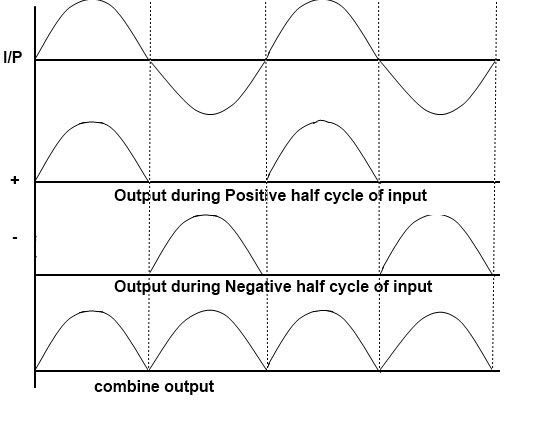
Explain its working and show the output, input waveforms.
(b) Show the output waveforms (Y) for the following inputs A and B of
(i) OR gate (ii) NAND gate


a.
The peak voltage of the output waveform is the same as before for the half-wave rectifier provided each half of the transformer winding have the same rms voltage. To obtain a different DC voltage output different transformer ratios can be used. The disadvantage of this type of full wave rectifier circuit is that a larger transformer for a given power output is required with two separate but identical secondary windings makes this type of full wave rectifying circuit costly compared to the Full Wave Bridge Rectifier circuit.

Given Circuit gives a overview on working of full wave rectifier. A circuit that produces the same output waveform as the full wave rectifier circuit a is that of the Full Wave Bridge Rectifier . Single phase rectifier uses four individual rectifying diodes connected in a closed loop bridge configuration to produce the desired output wave. The advantage of this bridge circuit is that it does not require a special center tapped transformer, so it reduces its size and cost. Single secondary winding is connected to one side of the diode bridge network and the load to the other side.
The four diodes labelled D1 to D4 are arranged in series pairs with only two diodes conducting current during each half cycle duration. When the positive half cycle of the supply goes, D1, D2 diodes conduct in a series while diodes D3 and D4 are reverse biased and the current flows through the load. During the negative half cycle, D3 and D4 diodes conduct in a series and diodes D1 and D2 switch off as they are now reverse biased configuration.Current flowing through the load is unidirectional mode and the voltage developed across the load is also unidirectional voltage, same as for the previous two diode full-wave rectifier model. Therefore the average DC voltage across the load is 0.637V.During each half cycle the current flows through two diodes instead of just one doide, so the amplitude of the output voltage is two voltage drops 1.4V less than the input VMAX amplitude, ripple frequency is now twice the supply frequency 100Hz for a 50Hz supply or 120Hz for a 60Hz supply.
b. Regards