can u please explain the working of full wave rectifier in detail and with some more explaination?

  • -1

A Full Wave Rectifier is a circuit, which converts an ac voltage into a pulsating dc voltage using both half cycles of the applied ac voltage. It uses two diodes of which one conducts during one half cycle while the other conducts during the other half cycle of the applied ac voltage.

During the positive half cycle of the input voltage, diode D1 becomes forward biased and D2 becomes reverse biased. Hence D1 conducts and D2 remains OFF. The load current flows through D1 and the voltage drop across RL will be equal to the input voltage.


During the negative half cycle of the input voltage, diode D1 becomes reverse biased and D2 becomes forward biased. Hence D1 remains OFF and D2 conducts. The load current flows through D2 and the voltage drop across RL will be equal to the input voltage.

  • 1

To get an output voltage for both half cycles of the input signal, we use full wave rectifiers. The commonly used full wave rectifier circuits are center-tap rectifier and bridge rectifier. The figure below shows the center-tap rectifier circuit.

Now consider the circuit. The P-side of the diodes D1 and D2 are connected to the secondary terminals of the transformer. The N-sides of the diodes are connected together. The load is connected between this point and the midpoint of the transformer. When the input signal to diode D1 is positive, it conducts and load current flows. During this time, the input to diode D2 is negative with respect to the midpoint. During the negative half cycle of the input signal, the voltage at D1 is negative and that at D2 is positive. So D2 conducts during this time period. Thus we get output voltage during both the half cycles. As the full wave rectifier rectifies both the half cycles, it is more efficient than the half wave rectifier. The waveforms are given below:

  • 0

Full Wave Rectifier

Well , the diagram might be a little complicated but it actually is not.

Now the speciality of the AC current is that its polarity changes (i.e. its terminals positive and negative switch places continuously) at an instant A is positive and B is negative and after some time B becomes positive and A becomes the negative terminals respectively.

Hence let us divide the whole function in two parts .

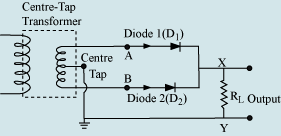
1. When A is the +ve part and B is the -ve part , in that case current will flow from A to B (positive to negative) , hence D1 becomes forward biased and D2 becomes reverse biased , therefore current will flow through D1 only and not D2 (ideal diodes has 0 resistance in forward biase and infinite resistance in reverse bias condition) , hence current flows in the load resistance R.

2. when A is negative and B is positive after a cycle current will flow from b to a (positive to negative) , hence D2 gets forward bias condition and D1 becomes in reverse bias condition, therefore current will flow from through D2 only and not in D1 and again current will flow through load resistance.

Hence as we see current flows through the load resestance in avary cycle (i.e. when A is +ve and B-ve and when Bis -ve and A is -ve) hence it is called full wave rectifier

  • 2
What are you looking for?